What is an emf potentiometer?

An emf potentiometer is a circuit used to measure the electromotive force (emf) of a cell without drawing current from it.

This is an advantage over using a voltmeter, which draws a small current and thus affects the terminal potential difference of the cell being measured.

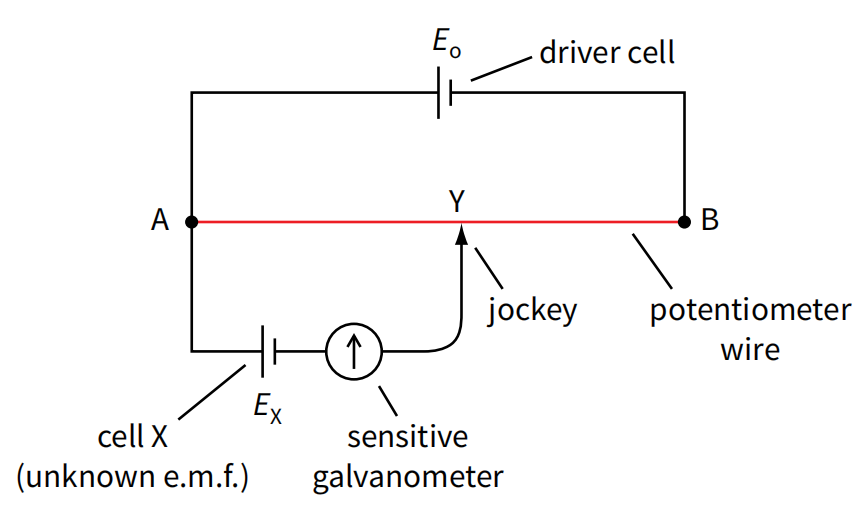
Components of an emf potentiometer

  • Driver Cell: A cell with a known and stable emf that provides the main voltage supply to the circuit. 
  • Test Cell: The cell whose emf (\(E_{x}\)) is to be measured. The cell must have a lower voltage than the driver cell.
  • Potentiometer Wire: A uniform resistance wire, stretched between two points (A and B). This wire acts as a uniform potential divider, meaning the voltage drops steadily along its length.
  • Jockey: A metal contact with a sharp edge that can be moved along the potentiometer wire to make contact at different points.
  • Sensitive Galvanometer: A device used to detect very small currents. It is used to indicate when the potentiometer circuit is balanced.
Mobirise Website Builder

Using a potentiometer

  • The driver cell (with emf E)is connected across A to B, creating a steady voltage drop along the wire.
  • When the jockey is close to point A, the galvanometer will deflect in one direction. When the jockey is close to point B, the galvanometer will deflect in the other. 
  • A point C will be found on the wire where touching the jockey causes zero deflection on the galvanometer. This is the balance point.
  • At this balance point, the potential difference across the portion of the wire between point A and point Y is exactly equal to the emf of the test cell (\(E_{x}\)).
  • If the length of the wire from A to the balance point C is AC, the emf of the test cell (\(E_{x}\)) can be calculated as: $$E_x = \left(\frac{AC}{AB}\right) \times E$$
Mobirise Website Builder